I have an old RCA 10W707 antenna rotator whose analog control unit I replaced
with a K3NG Arduino controller,
so I can point the antenna from the PC through hamlib’s rotctld. Driving the
motor with relays worked, reading the position potentiometer worked — but as
soon as the motor ran, the azimuth reading jumped around wildly, on the order
of ±20°.
Here’s how I tracked it down and fixed it with two resistors and two capacitors. Spoiler: the fix works — demo video.
The setup
The drive unit sits at the tower and connects to the control box over 35 m of 5-wire shielded cable. Two wires drive the two windings of a 20 V capacitor-run AC motor, one wire is shared by the AC common and the wiper of a 1 kΩ position pot, and two wires go to the ends of the pot’s track, fed with 5 V and GND. The Arduino reads the wiper through an RC filter on A0 — which works because the motor supply’s secondary floats at the wiper’s potential instead of being bonded to ground. (Correction: an earlier version of this post described the wiper as grounded and the reading taken from a track end — that was wrong.)
Root cause
My suspicion was that the motor current turns the common wire into a 50 Hz voltage generator — the pot’s wiper shares that wire with the motor’s return current, so the IR drop lands directly on the position signal. Measurements confirmed it:
- Motor winding currents: about 1 A each with the original controller, 1.5 A / 0.86 A with the new one (24 V secondary, 50 Hz). The two windings are ~90° apart in phase, so the common carries their vector sum, ≈1.7 A.
- Cable conductor resistances (35 m): motor wires 0.5 / 0.3 Ω, pot wires 1.3 / 1.2 Ω, and the common ≈0–0.2 Ω — I had bonded the cable shield in parallel with the common, which turned out to be load-bearing.
- The smoking gun, measured directly: 0.31 V AC between the drive-end common and the control-box DC− while the motor runs.
That 0.31 V rides on the pot signal almost 1:1, because the ADC measures relative to the Arduino’s local ground. My original “filter” made it worse: a 10 nanofarad cap on the wiper side followed by a series 1.2 kΩ to A0 — corner around 13 kHz, decent against RF pickup and completely transparent at 50 Hz, with the cap on the wrong side of the resistor to boot. The full 0.31 V (±0.44 V peaks) reached A0. The wiper sweeps ≈0.7–4.5 V across the travel — ≈3.8 V per 360° — so that’s ±29° of RMS jitter with ±40° peaks. Mechanism, magnitude and symptom all agreed.
The key insight
The disturbance is a zero-mean 50 Hz sine riding on the true signal, and nothing in the path clamps or rectifies before the filter (the ADC protection diodes sit behind it, where the ripple is millivolts). A passive RC low-pass is linear, so its output settles to the average — which is exactly the undisturbed position voltage. No bridge circuit, no differential amplifier needed: heavy 50 Hz rejection alone recovers a precise reading, even mid-rotation.
The fix: a two-stage RC filter
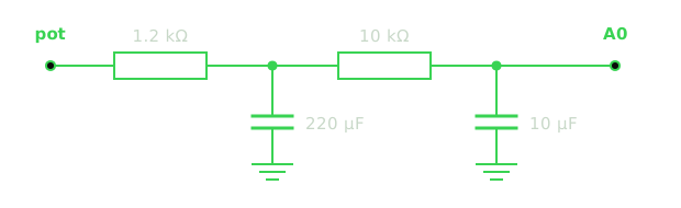
| Filter | Cutoff | 50 Hz rejection | Residual jitter | Lag |
|---|---|---|---|---|
| Old — 1.2 kΩ + 10 nF | ≈13 kHz | none | ±29° | ≈0 |
| Single stage — 1.2 kΩ + 220 µF | ≈0.6 Hz | ≈80× | ±0.4° | 0.26 s |
| Two-stage — + 10 kΩ + 10 µF | ≈0.5 Hz | ≈2500× | ±0.02° | ≈0.35 s |
A single stage would already have been usable, but the second one costs one resistor and one capacitor and keeps a big margin in case the shield bond ever corrodes in the field. The 0.3 s lag corresponds to about 2° at rotation speed, which the K3NG servo dead-band absorbs. The last capacitor sits directly at the A0 pin.
I built it, and the reading is now rock solid while the motor runs:
One quirk to be aware of: there is a ~2 s settling transient at power-up while the capacitors charge, during which the displayed heading ramps from full-CCW up to the true position. This is inherent — for any RC filter, settling time scales with the 50 Hz rejection — and harmless, since K3NG never rotates on its own at boot. Just don’t trust the display in the first two seconds.
Bonus findings from the measurement session
Putting a multimeter on everything paid off beyond the noise fix:
- The pot’s end stops leave ~10–15% of the track unused at each end (segments swing 106↔896 Ω and 152↔942 Ω). Harmless: K3NG calibrates to the actual endpoints.
- The winding current asymmetry (1.5 vs 0.86 A) is expected: the same winding is line-fed in one direction and fed through the 120 µF run capacitor in the other. The capacitor was sized for 60 Hz; the 50 Hz equivalent would be ≈144 µF, so paralleling an extra 25–30 µF motor-run cap would rebalance the phases — optional, the motor runs fine as-is.
- The motor pulls ≈41 VA from the transformer — an order of magnitude more than my first “small fan motor” estimate. The transformer needs to be ≥40 VA (or an 18 V secondary, which cuts current ~25% and motor heating ~45%), and the mains fuse a 315–400 mA slow-blow instead of the 125 mA fast-blow I had originally planned.
The lesson, as usual: measure first, then design. Every single round of measurements changed a number I had been confidently estimating.