After fixing the noisy position readings on my RCA 10W707 rotator, two itches remained. The relay-based motor drive has no speed control — the K3NG servo loop just bangs the motor on and off. And the whole controller hangs off a 230 V transformer, so no portable operation from the 13.8 V station supply or a LiFePO₄ battery.
Then came an idea I liked too much to let go: what if an audio amplifier drove the motor? A class-D or class-AB power amp is happy to output 50 Hz; controlling its input signal means controlling both frequency (speed) and amplitude (torque). A 13.8 V input with a boost converter instead of the mains transformer, and the battery problem dissolves too.
One insight leads to another
The 10W707 motor is a capacitor-run single-phase AC motor — which is really a two-phase motor wearing a disguise. The 120 µF run capacitor is nothing but a poor man’s 90° phase shifter, and it’s only correct at one single frequency.
So don’t use one amplifier channel — use two, in true quadrature: one winding gets sin, the other gets cos. Then:
- the phase shift is exactly 90° at every frequency → full torque from a ~5 Hz crawl up to the 60 Hz design speed of the motor;
- the run capacitor disappears;
- the direction relays disappear too — reversing is flipping the sign of one channel’s phase in software;
- the winding currents become symmetric.
One catch: the windings share their common wire inside the drive unit (3-wire motor), so bridge-tied (BTL) class-D modules are out — their output legs can’t share a conductor. The plan is two TDA7294 class-AB chips in single-ended single-supply mode (~52 V from a boost converter), output coupling caps, motor common to ground. Class AB also means zero switching hash on 35 m of cable at a radio site.
The firmware had to be rewritten anyway
The K3NG build fills 99.7% of the Nano’s flash. I measured what enabling just its variable-frequency outputs costs: 102.3% — doesn’t link. And no firmware on Earth generates two synchronized quadrature sines with a V/f amplitude law out of the box, so I rewrote the whole thing from scratch: a GS-232A subset for rotctld, the servo loop, LCD, buttons, and the quadrature DDS — Timer1 dual PWM at 62.5 kHz carrier, an 8 kHz update interrupt stepping a 256-entry sine table twice, 90° apart. It builds to 6.9 KB: 22% of flash instead of 99.7%.
The measurement setup
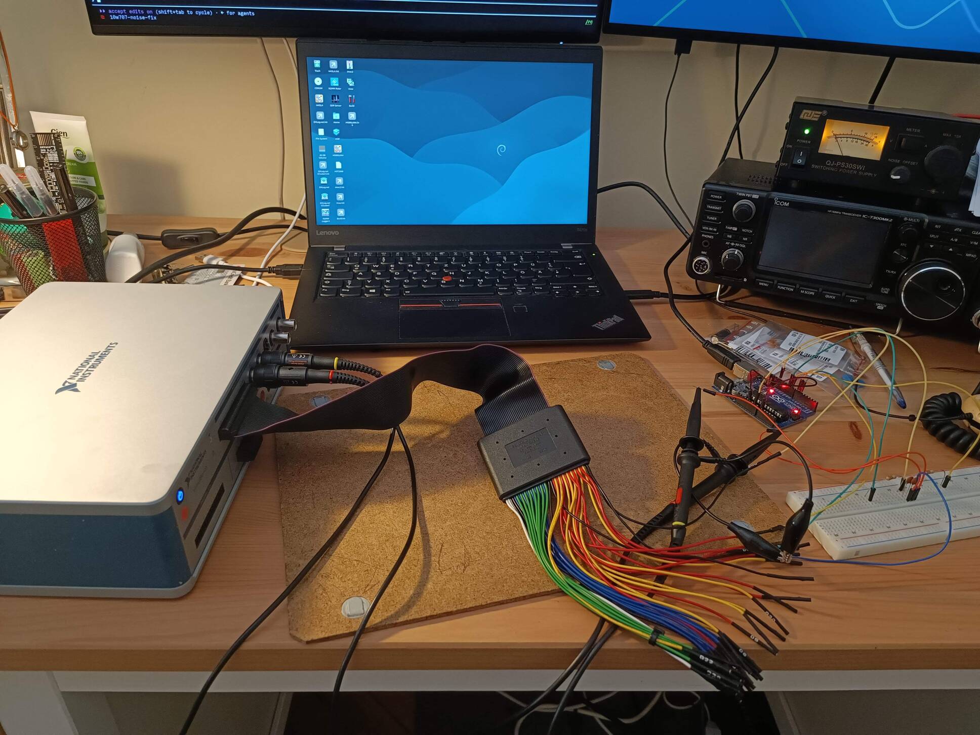
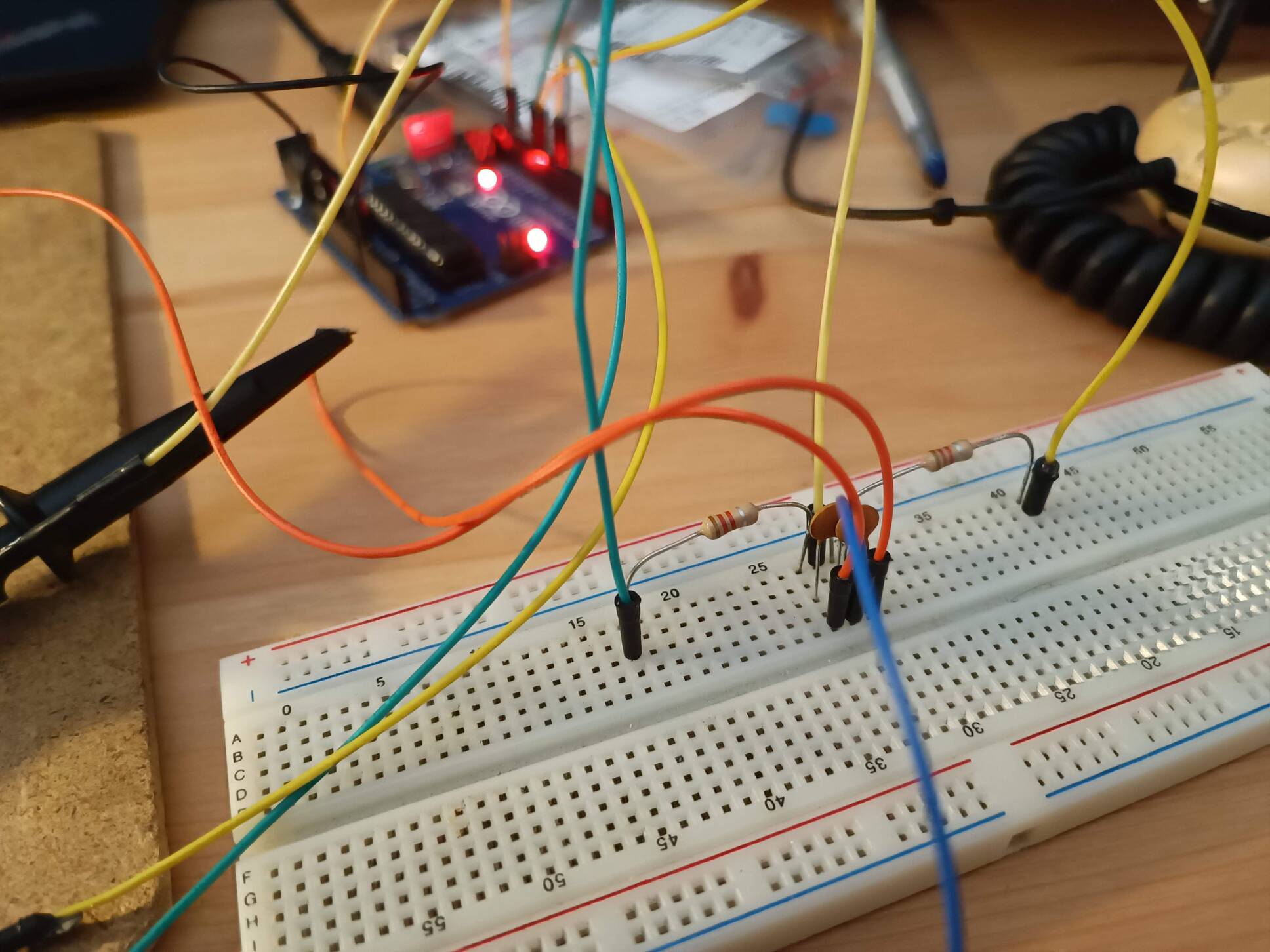
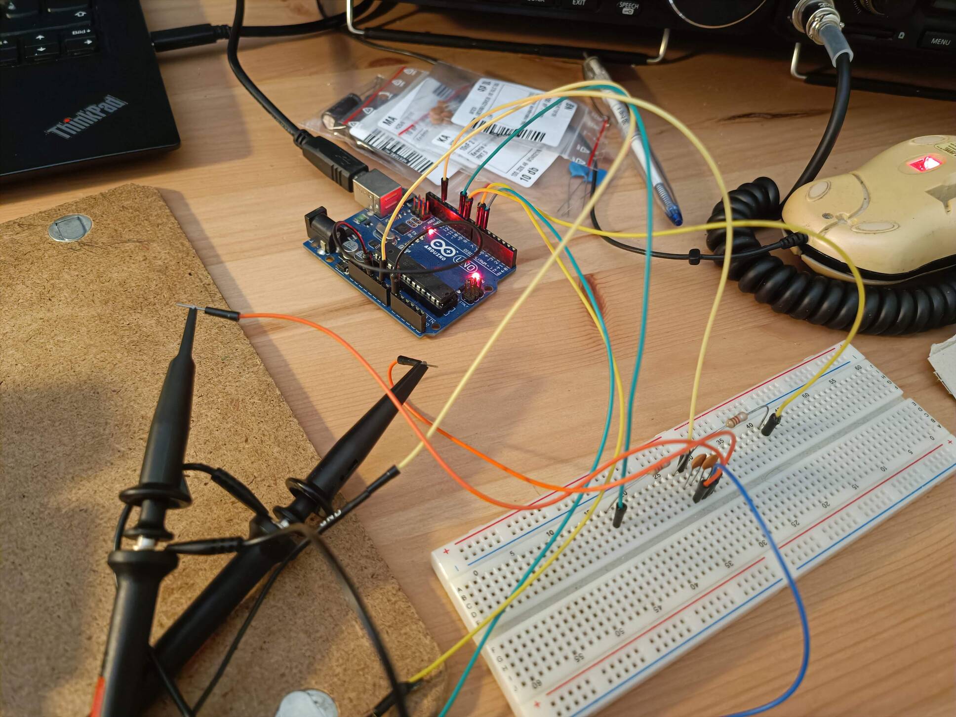
Signal-only bench test: a spare Arduino Uno (same ATmega328P as the wired-in Nano), a 1.2 kΩ + 100 nF RC filter per channel to strip the PWM carrier, and my NI VirtualBench VB-8012 mixed-signal scope. The NI software is Windows-only, so it runs in a VirtualBox VM that grabs the instrument over USB — while the Uno stays on the Linux side, driven over serial with GS-232 commands. CH1/CH2 on the two DDS outputs, and two logic-analyzer channels on the amplifier MUTE/STBY control lines.
The measurements
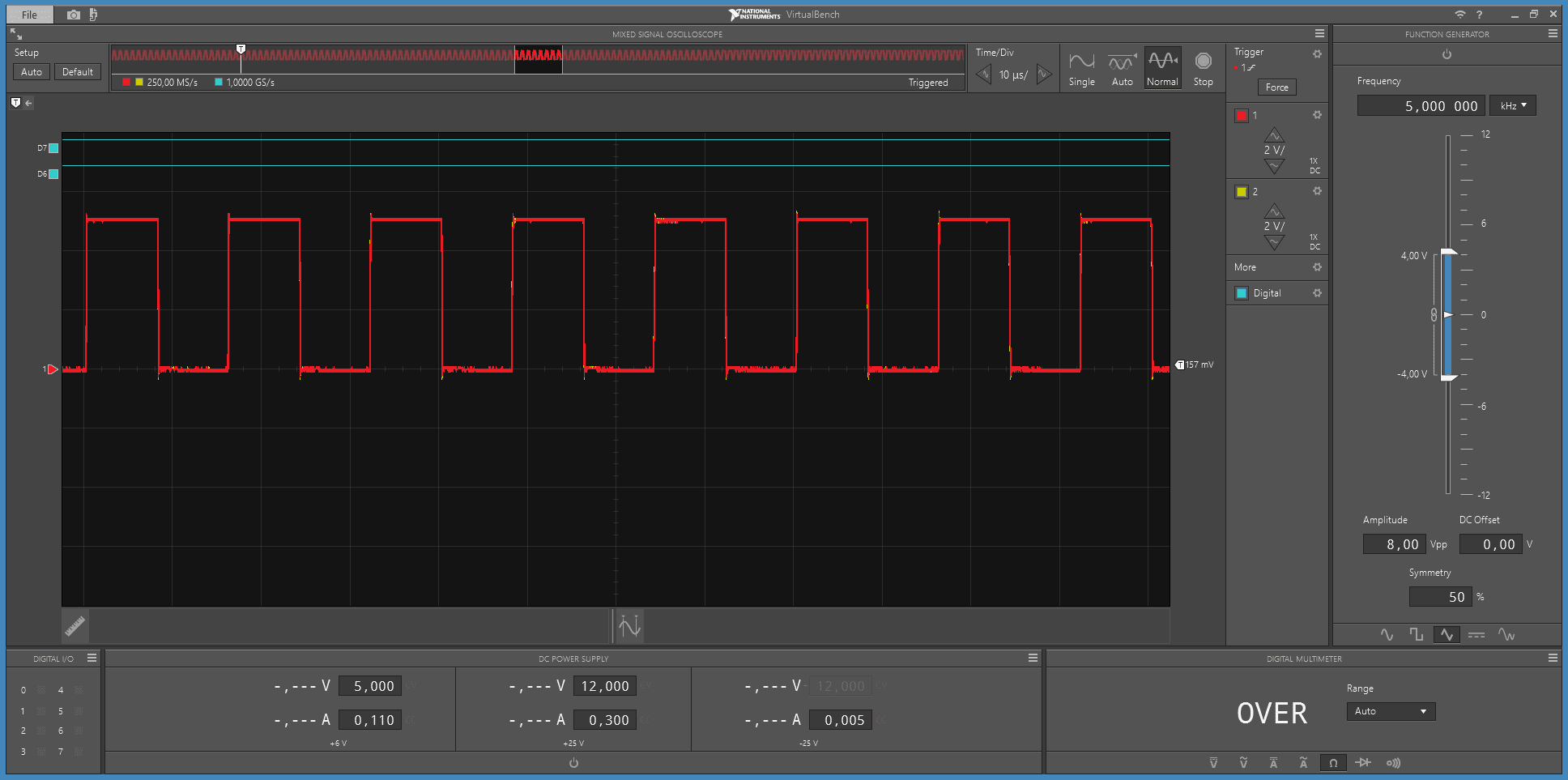
Before the RC filters, the raw output is just the idle PWM carrier: 62.5 kHz at 50% duty on both pins — this is what the amplifier would see without a filter, and why the filter exists:
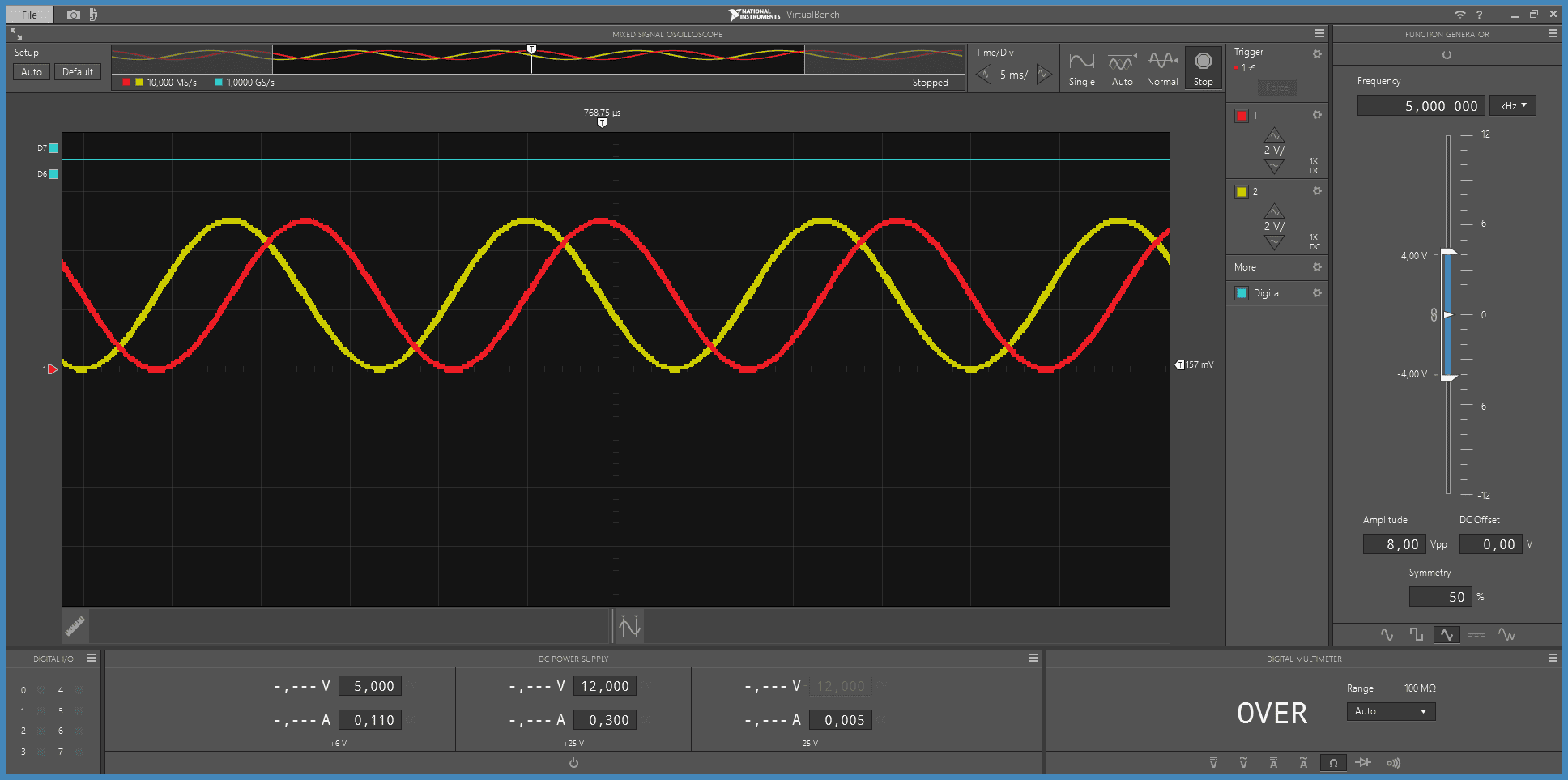
Command R (rotate CW): two clean 60 Hz sines, ~5 Vpp, centered on 2.5 V,
with the cosine channel leading by exactly 90°:
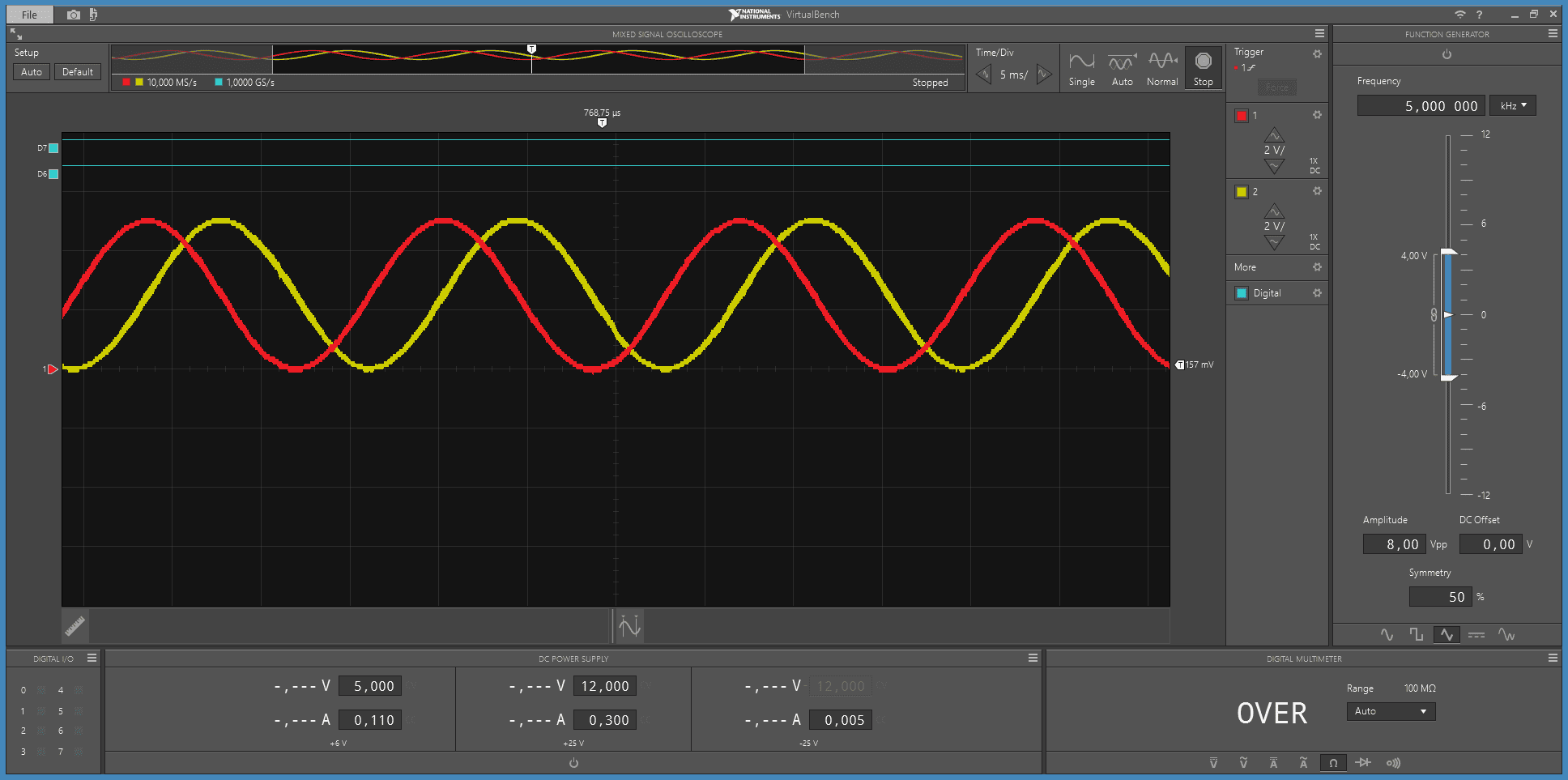
Command L (rotate CCW): the mirror image — cosine now lags by 90°.
The entire relay board of the old design, replaced by a sign flip:
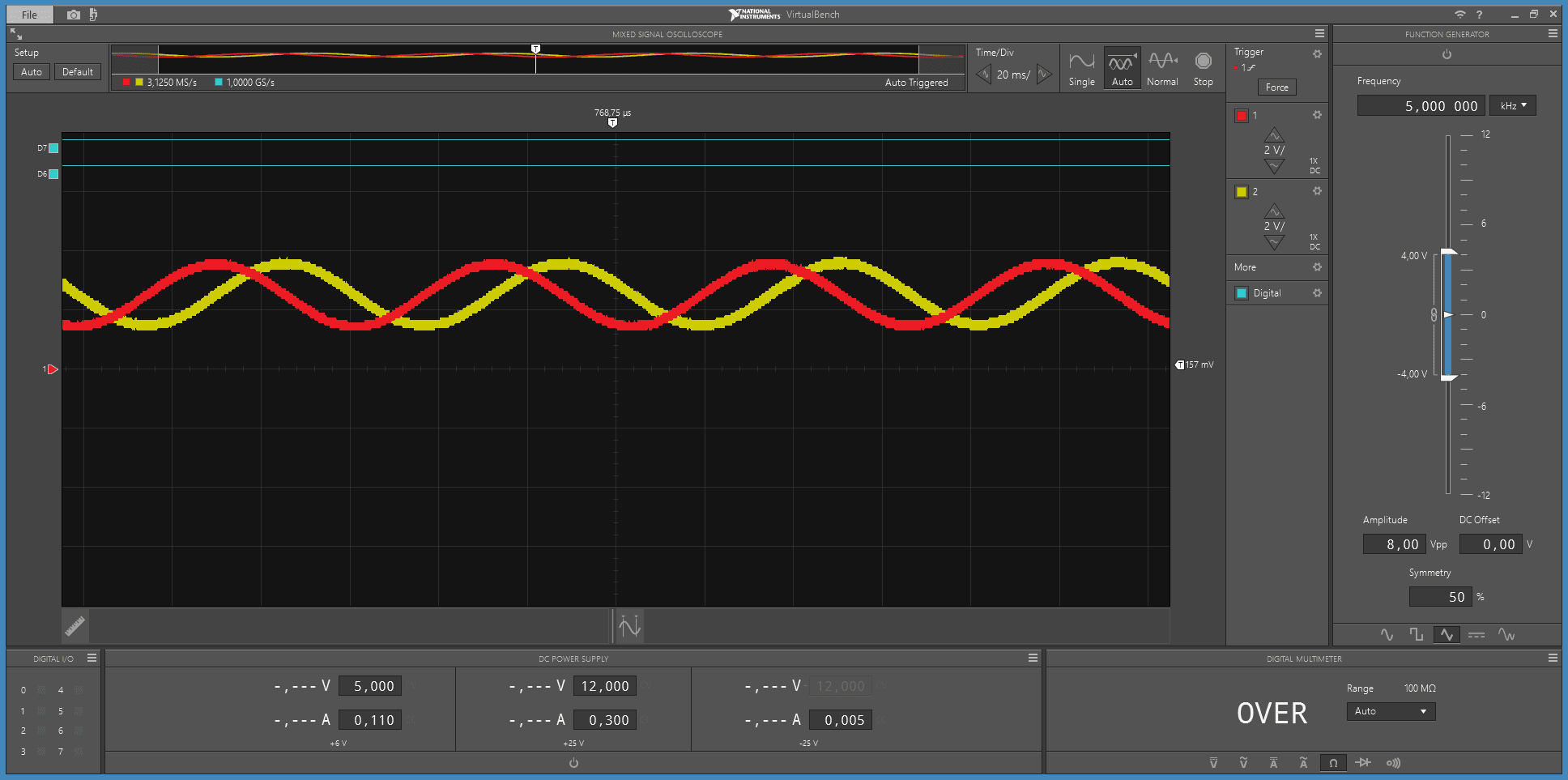
Parking the servo in its approach-taper zone (M357 with the position input
pinned): ~16 Hz at ~2 Vpp. That’s the V/f law visibly holding motor flux
constant at low speed:
Soft start: the MUTE/STBY lines release first, then the amplitude ramps from zero to full in about half a second, quadrature intact the whole way:
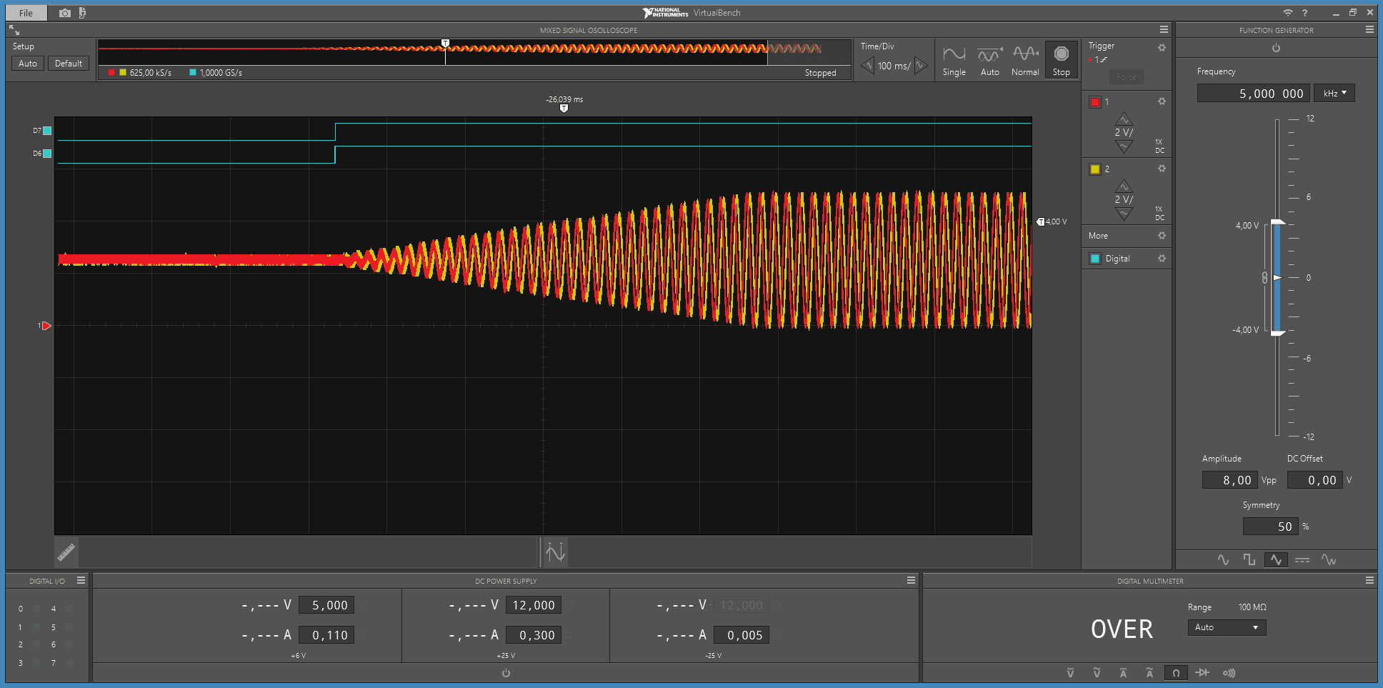
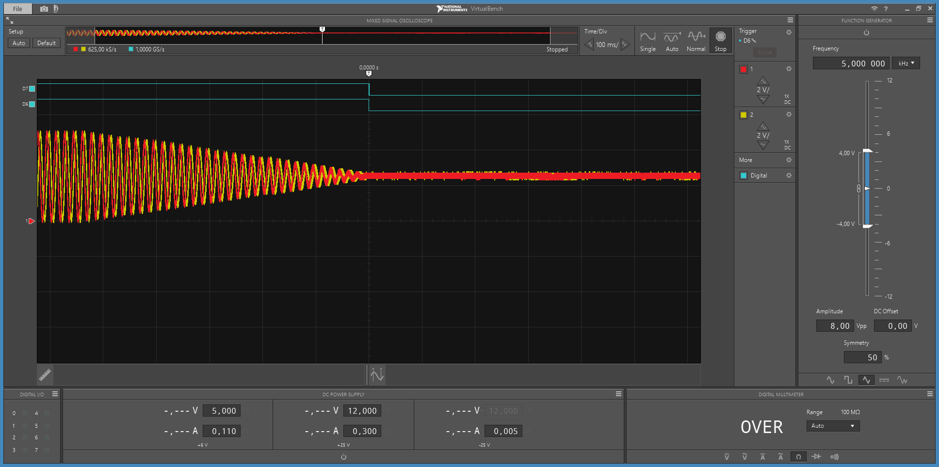
Soft stop, captured by triggering on the falling MUTE line: half a second of smooth decay to a flat 2.5 V, and the mute drops only after the amplitude reaches zero. No motor jerk, no amplifier thump:
Verdict
Every number matched prediction: frequency, amplitudes, the ±90° phase flip, the V/f tracking, the ramp timing, the mute sequencing. The complete signal side of a two-phase variable-frequency drive — proven on a breadboard with two resistors and two capacitors.
Next up: the power stage. Two TDA7294s on perfboard, a 13.8 → 52 V boost module, a dummy load test — and then the motor gets to vote.